Intelligent Control System for Efficient Energy Management in the Oil and Gas Industry
The question
What does automated climate control need where ventilation is also a gas-safety system?
At oil and gas sites in regions with hot summers and harsh winters, heating, ventilation, and air conditioning (HVAC) protect workers and equipment while ventilation clears hazardous gas before it builds up. A wall thermostat with fixed settings cannot capture conditions everywhere people work or gas may collect. We investigated what an automated system needs to sense, decide, and control to bring comfort, equipment temperature, and gas alarms into one feedback loop.
What we built
We built a test platform in which 11 sensors, including leak detectors, feed a controller that switches heaters, air conditioners, fans, and valves. Industrial and wireless protocols carry readings to supervisory software, where an operator can follow the process and adjust it locally or remotely. Gas-leak signals can trigger emergency ventilation and protection automatically.
Schematic overview
Connecting the physical controller to the operator’s screen
Measure the room and equipment
Read temperature, humidity, pressure, air-flow, and gas signals. These measurements describe current conditions; they are the inputs to monitoring and control.
Send commands to physical devices
The controller and its input/output connections link readings to equipment such as heaters, fans, and dampers. New sensor readings provide feedback after an adjustment.
Let operators inspect and adjust
A supervisory screen displays readings and equipment status, records changes, and provides controls. It communicates with the controller rather than replacing the physical control hardware.
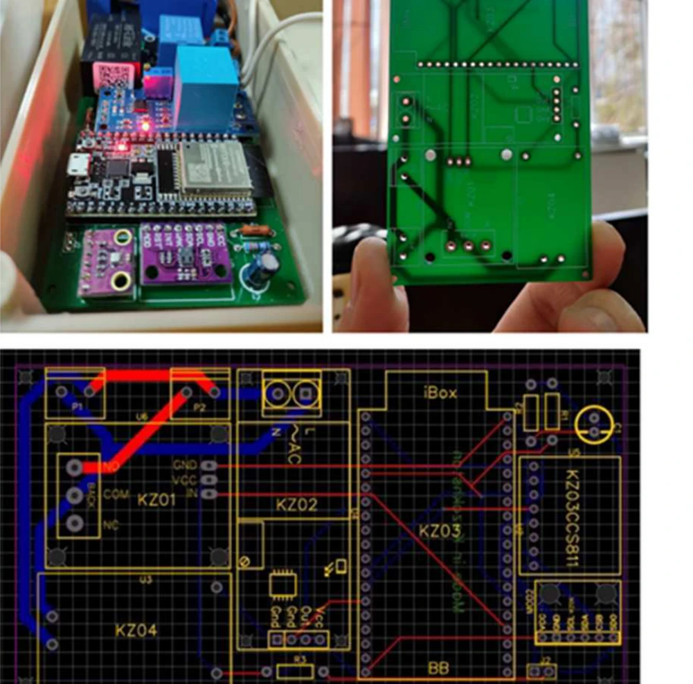
The hardware that collects and acts
The upper photographs show the prototype’s populated electronics and circuit board. The lower image is the board layout. This is the physical interface to sensors and control signals.
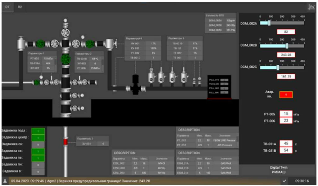
The software an operator uses
The original screen shows the ventilation process, current values, status indicators, and controls. Its labels are partly in Russian. The interface lets an operator inspect conditions, change settings, and use an emergency button.
Figure details and test conditions
These are engineering records from the test platform: the control and data-acquisition module with its circuit design, then the operator’s SCADA (supervisory control and data acquisition) screen. They show what was built and how an operator uses it, rather than energy-use or prediction results.
Figure 4, PDF page 4; Figure 5, PDF page 5 from the paper (opens in a new tab)
Climate control and gas safety at industrial sites
Heating and ventilation are among the largest energy uses in buildings. In US commercial buildings in 2018, space heating took about 32% of all energy and ventilation about 10% (US EIA). At oil and gas facilities, the same equipment also does safety work. Hazardous gases and vapours can accumulate indoors, and ventilation helps keep them below dangerous levels. The international standard for classifying explosive-gas areas takes into account how well, and how reliably, a space is ventilated (IEC 60079-10-1). Equipment and stored materials often need a controlled temperature too, in regions with hot summers and harsh winters.
Bringing these requirements into an automated system requires measurements across the space. A single wall thermostat, often far from where people work, cannot represent all of those conditions. The controller needs readings from many points, including gas levels, and it has to keep alarms and emergency ventilation working alongside any energy-saving logic. The system also has to connect industrial controllers, wireless sensors, databases, and operator software, each with its own communication protocols.
Connecting sensing, control, and monitoring
The test platform has 11 sensors, including temperature sensors and leak detectors, and monitors carbon dioxide and indoor air quality. A control cabinet with a Siemens SIMATIC S7-1200 controller and input/output modules switches heaters, air conditioners, fans, dampers, and valves. Wireless sensors report over LoRaWAN through a base station. Devices exchange data over Modbus TCP, and an OPC UA server groups similar parameters into typed templates so the software interface can be configured without listing every device by hand.
The paper sets out the control process step by step: collect data, compare it with set ranges, decide, execute commands, and monitor the response. An intelligent component built with neural-network, XGBoost, and Random Forest models supports the analysis. A dedicated controller handles safety, connecting a safety valve and triggering emergency ventilation and protection when sensors detect a gas leak. The operator follows all of this in Genesis64, the supervisory control and data acquisition (SCADA) software, and can adjust settings locally or remotely.
Scope of the study
This is a design and implementation report from one test platform. It documents how the sensors, controllers, communications, and SCADA screen connect, and what each does.